Features of Smart SVC System
- New and effective solution in compensation
- Long maintenance period and complete solution in panels
- Uninterrupted and complete solution to variable loads
- Fewer steps (capacitor, reactor, contactor, fuse..)
- Thanks to automatic step test, compensation with constantly updated and step values
- Longer capacitor and contactor life as step changes will be reduced
- Rates far below the penalty limits, target “0” inductive and capacitive values
- Effective solution even in businesses with welding, crane and spot machines
Relay Models
1) Smart 12CL - COM
- 12 contactor outputs
- A single-phase/di-phase/three-phase capacitor or shunt reactor can be connected to each stage.
- 200ms response time
- 3 mA detection current
- Power Flow Chart that records the reactive energy consumption of the business with its durations
- 144X144X100 (WXHXD)
- User-friendly Turkish menu
- Automatic Step Recognition and Step Test
- High precision power measurement with 24-bit resolution
- RS 485 output
- Remote access and intervention to all parameters
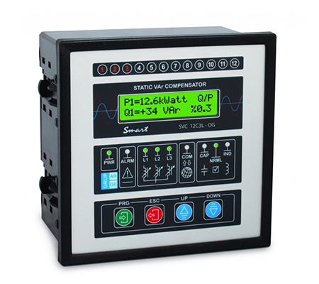
2) Smart SVC12C3L - COM
General Information
Smart SVC12C3L is a new generation compensation relay. Contrary to conventional compensation relays, it does not try to respond to the system by using only capacitor stages, but also activates it by adjusting the powers of the coils (shunt reactor) that provide inductive load. In this way, it responds to the system much faster and more fully than conventional relays.
Since classical relays have a certain number of capacitors, they cannot fully meet all the reactive powers required by the system, it only tries to find the closest possible value. In addition, since the switching is made by means of mechanical contactors, its ability to respond to fast in and out loads is limited. Smart SVC, on the other hand, fully meets the needs of the system by opening its inductive coils at the desired power for each phase. Since the switching is done with thyristors, the response time to the system is very short. Thanks to this method, Smart SVC can easily compensate the system even in enterprises where conventional compensation relays are difficult.
Technicial Specifications
- 12 contactor outputs
- A single-phase/di-phase/three-phase capacitor or shunt reactor can be connected to each stage.
- 3 thyristor-controlled reactor stages (Each reactor can be commissioned as 1000 separate stages)
- >200 ms response time
- 3 mA detection current
- Power Flow Chart that records the reactive energy consumption of the business with its durations
- 144X144X100 (WXHXD)
- User-friendly Turkish menu
- Automatic Step Recognition and Step Test
- High precision power measurement with 24-bit resolution
- RS 485 output
- Remote access and intervention to all parameters
3) Smart SVC12C3L - OG
General Information
Businesses that need high power need to take power transformers into their own structure. In this case, depending on the magnitude of the power, the electricity meter is placed on the medium voltage side. In the enterprises where the meter is on the medium voltage side, in case of high power consumption, the compensation made on the low voltage side is sufficient to solve the reactive problem. However, in cases where the active consumption decreases, the compensation made by the low voltage cannot prevent the enterprise from penalizing.
At the root of this problem
- The transformer constant cannot be adjusted according to the changing current,
- Inadequate sensitivity classes of current transformers and measuring equipment at low currents,
- The phase imbalance observed in the unloaded transformer creates a disruptive effect on the reactive energy in both inductive and capacitive directions on the medium voltage side.
- There are details such as the presence of long lines between the meter and the transformer.
Smart SVC – MV compensation relay has been developed as a result of experience and long efforts in the fields to solve this problem. The MV relay receives current information from 3 current transformers on the medium voltage side or to be newly installed. Voltage information is taken by the low voltage side and the power of each phase is measured independently, taking into account the phase angle difference. As a result of this measurement, the relay produces a solution on the low voltage side of the system by using both the existing stages and the SVC outputs.
After the application, as a result of the observations to be made from the counter and the relay, the reactive problem can be completely eliminated by making precise adjustments on the phases. It is also very useful to see the Cos fi values or reactive powers of each phase on the meter screen on the medium voltage side.
Technicial Specifications
- 12 contactor outputs
- A single-phase/di-phase/three-phase capacitor or shunt reactor can be connected to each stage.
- 3 thyristor-controlled reactor stages (Each reactor can be commissioned as 1000 separate stages)
- 200ms response time
- 3 mA detection current
- Power Flow Chart that records the reactive energy consumption of the business with its durations
- 144X144X100 (WXHXD)
- User-friendly Turkish menu
- Automatic Step Recognition and Step Test
- High precision power measurement with 24-bit resolution
4) Smart SVC12C3L - FAST
General Information
It is a special solution that can be applied for systems where loads are variable and phase differences are different and fluctuate relatively fast and with low amplitude. The response time of the reactors in this solution is 20 ms. In such systems, by using the advantage of SVC, both the system will be responded quickly and a more cost-effective solution will emerge. In such systems, it is more appropriate to use thyristor switched modules (See SVC22CL)
Technicial Specifications
- 12 contactor outputs
- A single-phase/di-phase/three-phase capacitor or shunt reactor can be connected to each stage.
- 3 thyristor-controlled reactor stages (Each reactor can be commissioned as 1000 separate stages)
- 20 ms response time
- 3 mA detection current
- Power Flow Chart that records the reactive energy consumption of the business with its durations
- 144X144X100 (WXHXD)
- User-friendly Turkish menu
- Automatic Step Recognition and Step Test
- High precision power measurement with 24-bit resolution
- RS 485 output
- Remote access and intervention to all parameters
5) Smart SVC18C3L - TRI
General Information
In unstable businesses where reactive changes are fast and large, systems with contactors are insufficient to respond to the need for compensation. In the compensation of such enterprises, it is possible to respond to rapidly changing loads by switching with thyristor instead of switching with mechanical contactors in classical systems. In addition, when the capacitors are commissioned for the first time, since the current drawn is minimum, it is possible to switch on and off at a high speed. With this system, the life of the capacitor and switching elements is extended and the power quality is positively affected. In addition, maintenance costs are minimized. The system can operate in both binary mode and normal mode, depending on the power of the connected capacitors. If the capacitor arrangement is made in such a way that each step is 2 times the previous step, the system is considered as binary. In binary mode, capacitor selection is done much faster. If desired, the system that will be created without a binary sequencing in this way accepts the relay as normal mode and produces a solution accordingly. The system detects the load change in 10 ms and makes it possible to switch within the next 10 ms. At the first zero crossing after the switching signal, the capacitor is activated (<20 ms). In this way, the response rate of the system is pulled up to 50 ms.
Technicial Specifications
- 18 PNP outputs
- A single-phase/di-phase/three-phase capacitor or shunt reactor can be connected to each stage.
- 3 thyristor-controlled reactor stages (Each reactor can be commissioned as 1000 separate stages)
- 20 ms response time
- 3 mA detection current
- Power Flow Chart that records the reactive energy consumption of the business with its durations
- 144X144X100 (WXHXD)
- User-friendly Turkish menu
- Automatic Step Recognition and Step Test
- High precision power measurement with 24-bit resolution
Usage areas
- In enterprises with CNC machines
- In lathe-leveling workshops
- In enterprises with presses
- In workshops with spot and welding machines
- In enterprises with elevator systems
6) Smart SVC22CL - TRI
General Information
In unstable businesses where reactive changes are fast and large, systems with contactors are insufficient to respond to the need for compensation. In the compensation of such enterprises, it is possible to respond to rapidly changing loads by switching with thyristor instead of switching with mechanical contactors in classical systems. In thyristor systems, since the capacitors are activated at zero crossings, the necessity of waiting for discharge times is eliminated. In addition, when the capacitors are activated for the first time, since the current drawn is minimum, it is possible to switch on and off at a high speed. With this system, the life of the capacitor and switching elements is extended and the power quality is positively affected. In addition, maintenance costs are minimized. The system can operate in both binary mode and normal mode depending on the power of the connected capacitors. If the capacitor arrangement is made in such a way that each step is 2 times the previous step, the system is considered as binary. In binary mode, capacitor selection is done much faster. If desired, the system that will be created without a binary sequence in this way, the relay accepts as normal mode and produces a solution accordingly. The system detects the load change in 10 ms and makes it possible to switch within the next 10 ms. At the first zero crossing after the switching signal, the capacitor is activated (<20 ms). In this way, the response rate of the system is pulled up to 50 ms.
Technicial Specifications
- 22 PNP outputs
- A single-phase/di-phase/three-phase capacitor or shunt reactor can be connected to each stage.
- 20 ms response time
- 3 mA detection current
- Power Flow Chart that records the reactive energy consumption of the business with its durations
- 144X144X100 (WXHXD)
- User-friendly Turkish menu
- Automatic Step Recognition and Step Test
- High precision power measurement with 24-bit resolution
Usage areas
- In enterprises with CNC machines
- In lathe-leveling workshops
- In enterprises with presses
- In workshops with spot and welding machines
- In enterprises with elevator systems